
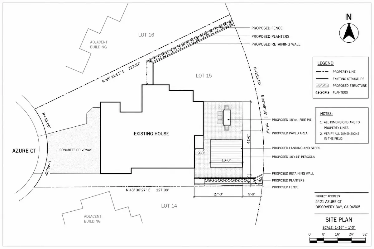
If you’ve never seen a permit site plan before — or if you want to understand what separates a plan that passes review from one that gets sent back — this guide walks through every element of a well-prepared site plan.
I’m Engineer Wasim of Site Plans Online USA. My team prepares permit site plans across all 50 states. Here’s what a correct, complete site plan looks like in practice.
What a Permit Site Plan Looks Like from Above
Imagine looking straight down at your property from above. You can see the lot boundaries, the house, the driveway, the backyard. That’s your starting point.
A permit site plan is that view — drawn to scale on paper (or digital drawing), with every important element labeled. The key word is “to scale” — everything drawn in consistent proportion so a reviewer can verify actual distances.
The Elements of a Well-Prepared Site Plan: Annotated
1. The Outer Boundary — Lot Lines
The lot lines form the outer boundary of your property on the drawing. They are thick lines with dimensions labeled on each side in feet.
What a good site plan shows:
- All four lot lines (or more for irregular lots)
- Each side’s length in feet
- The front property line identified (facing the street)
What a common mistake looks like:
- Lot lines with no dimensions
- A rough rectangle that doesn’t reflect actual lot shape
- No distinction between front, rear, and side property lines
2. The Property Identifiers — Top of Drawing
Near the top or in the title block, a well-prepared site plan shows:
- Full property address: “123 Main Street, Tampa, FL 33601”
- APN/Parcel ID: “Parcel No. 12-34-567-890”
- Owner name: “John Smith”
- Preparer: “Site Plans Online USA”
- Date: “May 2026”
- Scale: “1” = 20′”
3. The North Arrow — Corner of Drawing
A clear north arrow, labeled “N,” in one corner of the drawing. It tells the reviewer which direction is north so they can identify front yard (street-facing), rear yard, and side yards.
4. The Scale Bar — Near the North Arrow
A graphic scale bar — a small horizontal ruler showing measured distances. Example: a bar with tick marks at “0, 10, 20, 30 feet.” This lets the reviewer verify any dimension by measuring it against the bar.
5. Existing Structures — Everything That’s There Now
On a well-prepared site plan, every structure on the lot is shown:
- Main house — drawn as an accurate rectangle (or shape) with dimensions
- Attached garage — part of the house footprint
- Detached garage — shown separately with dimensions
- Existing pool — shown with water edge, deck edge, and any existing barrier
- Shed — shown with dimensions
- Driveway — the full paved area outlined
- Existing patios, concrete slabs — shown
Why this matters: Reviewers cross-check against satellite imagery. Anything visible from above that isn’t on the plan = correction notice.
6. The Proposed Project — What’s New
The proposed new construction is drawn distinctly from existing structures:
- Typically shown with dashed lines or different line weight
- Labeled clearly: “PROPOSED POOL,” “PROPOSED DECK,” “PROPOSED ADDITION”
- Fully dimensioned: every length and width labeled
7. Setback Dimension Arrows — The Most Critical Element
This is the most important part of any permit site plan. Four dimension arrows show:
- Distance from proposed structure → front property line
- Distance from proposed structure → rear property line
- Distance from proposed structure → left side property line
- Distance from proposed structure → right side property line
Each arrow has the distance in feet labeled at its midpoint.
What a rejected plan looks like: These arrows are missing one or more sides, or the distances are shown visually but not labeled with a number.
8. The Impervious Surface Calculation Box
In a corner of the plan, a small table or text block showing:
| Lot Area: | 8,500 sq ft |
| Existing Coverage: | 2,600 sq ft |
| Proposed New: | 750 sq ft |
| Total Coverage: | 3,350 sq ft |
| Coverage %: | 39.40% |
| Zone Maximum: | 55.00% |
9. Project-Specific Elements
For pool plans: Pool barrier shown as a dashed line around the pool area, with barrier height labeled (“Proposed barrier: 4 ft high, self-closing/self-latching gates per IRC”), and equipment pad shown.
For fence plans: Fence line shown following property lines with height labeled and gate locations marked.
For commercial plans: Parking layout with space count, ADA spaces labeled, fire lane shown.
What a Plan That Passes Review Has vs. One That Doesn’t
| Element | Passes Review | Gets Rejected |
|---|---|---|
| Scale | 1″=20′, graphic bar shown | “Not to scale” or bar missing |
| Setbacks | All 4 labeled with feet | 1–2 missing |
| Existing structures | All shown | Shed, patio, or pool missing |
| Impervious surface | Calculation shown | Not mentioned |
| North arrow | Present, labeled | Absent |
| Title block | All fields complete | Missing APN or date |
| Project labeling | “PROPOSED” clear | Looks same as existing |