
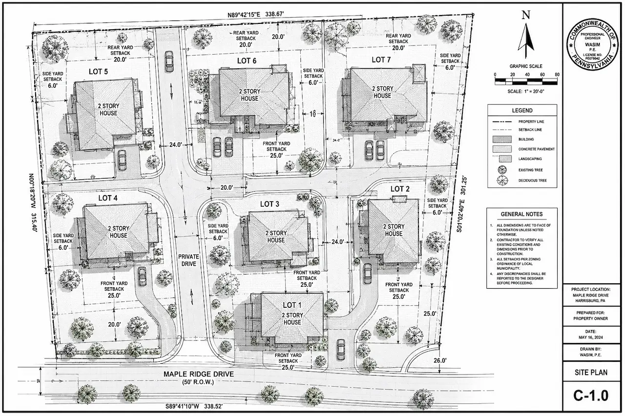
A site plan can look confusing when you first open it. It may contain property lines, measurements, symbols, setback dimensions, easements, utility locations, and notes that are unfamiliar to most homeowners.
This guide explains how to read a site plan before submitting it for a building permit, reviewing work from a drafter, or discussing a project with a contractor or building department.
To read a site plan, start with the title block and drawing scale. Then locate the north arrow, identify the property boundaries, use the legend to understand symbols, distinguish existing structures from proposed work, and review setbacks, easements, utilities, access, drainage, and lot-coverage information.
Requirements and drawing conventions vary between jurisdictions, so always compare your plan with the official city or county permit checklist.
What Is a Site Plan?
A site plan is a scaled, top-down drawing of a property. It shows the relationship between the lot boundaries, existing site conditions, proposed construction, streets, driveways, utilities, easements, and other relevant features.
Unlike a floor plan, which shows the interior layout of a building, a site plan shows how the entire project fits on the property.
Homeowners commonly need site plans for:
- Home additions
- Garages and sheds
- Pools and decks
- Fences and driveways
- Accessory dwelling units
- New construction
- Commercial improvements
- Permit corrections
Use the USA Permit Requirements Checker to review common location-specific requirements before submitting your drawing.
How to Read a Site Plan in 10 Steps
1. Start With the Title Block
The title block is normally located along the bottom or side of the drawing. It identifies the plan and provides important project information.
Check for:
- Property address
- Owner or applicant name
- Project description
- Parcel or folio number
- Drawing scale
- Date prepared
- Revision date
- Sheet number
- Preparer’s name and company
- Professional license or seal, when required
Always confirm that you are reviewing the latest revision. An outdated sheet may not include changes requested by the building department.
2. Confirm the Drawing Scale
The scale shows how measurements on the drawing relate to actual distances on the property.
For example:
Scale: 1 inch = 20 feet
This means one inch measured on the printed plan represents 20 feet on the property.
A permit plan may also include a graphic scale bar. This helps verify the scale if the plan has been printed or resized.
Do not measure directly from a computer screen unless the PDF scale and page size are confirmed. Permit site plans generally need a stated, usable scale, but the accepted scale may vary by jurisdiction and lot size.
3. Find the North Arrow
The north arrow shows the orientation of the property.
Use it to identify:
- Front of the lot
- Rear yard
- Left and right side yards
- Street location
- Direction of surrounding features
Do not assume the top of the page is north. The drawing may be rotated to fit the property on the sheet.
4. Identify Property Lines and Lot Dimensions
Property lines define the outer boundaries of the lot. They are often shown with heavier, distinctive, or labeled lines.
Look for:
- Front property line
- Rear property line
- Side property lines
- Length of each boundary
- Lot width and depth
- Total lot area
- Bearings or directional notation
- Adjacent streets or rights-of-way
A site plan represents property-boundary information, but it is not automatically the same as a legal boundary survey. Confirm whether your permitting authority requires a survey prepared by a licensed land surveyor.
5. Use the Legend to Read Symbols and Line Types
The legend explains the symbols, abbreviations, and line patterns used on the plan.
Depending on the drawing, the legend may identify:
- Existing structures
- Proposed structures
- Setback lines
- Easements
- Utility lines
- Drainage features
- Fences
- Trees
- Demolition areas
- Property boundaries
Do not assume dashed or dotted lines always have the same meaning. Drawing conventions vary between drafting companies and jurisdictions. Always check the legend and plan notes.
6. Separate Existing and Proposed Work
The plan should clearly distinguish what currently exists from what will be added, altered, or removed.
Existing conditions may include:
- Main house
- Garage
- Shed
- Pool
- Patio
- Deck
- Fence
- Driveway
- Walkway
- Retaining wall
Proposed work should be clearly labeled, dimensioned, and visually distinct.
Confirm that every major structure on the property is shown. An omitted shed, driveway, patio, or accessory structure may lead to permit corrections.
7. Review Setbacks and the Buildable Area
A setback is the required distance between a structure and a property line, street, right-of-way, or other regulated feature.
Site plans commonly show:
- Front setback
- Rear setback
- Left-side setback
- Right-side setback
- Distance between buildings
- Distance from pools, septic systems, utilities, or easements
Check that the proposed project has clearly labeled dimensions from the relevant property lines.
Measurement rules vary. Some jurisdictions measure to the exterior wall, while others may require measurements to roof overhangs, deck edges, pool waterlines, or another defined project boundary.
8. Locate Easements, Rights-of-Way, and Utilities
An easement is a defined portion of a property where another party may have access or usage rights.
Common examples include:
- Utility easements
- Drainage easements
- Access easements
- Ingress and egress easements
- Conservation easements
The site plan may also show:
- Water lines
- Sewer connections
- Septic tanks
- Drain fields
- Wells
- Electrical service
- Gas lines
- Overhead utilities
Proposed construction may be restricted within an easement. Confirm any uncertainty with the building department, utility provider, surveyor, or other qualified professional.
9. Review Access, Drainage, and Site Conditions
Check how people, vehicles, and water move across the property.
The drawing may include:
- Driveway width and location
- Street access
- Parking areas
- Sidewalks
- Fire-access routes
- Drainage swales
- Ditches
- Stormwater facilities
- Contour lines
- Slopes
- Flood zones
- Waterways
- Existing trees
Contour lines represent changes in ground elevation. Closely spaced contours usually indicate a steeper slope, while wider spacing generally indicates flatter ground.
Projects involving grading, drainage, retaining walls, or significant slopes may require additional engineering information.
10. Check Lot Coverage, Notes, and Revisions
Lot coverage and impervious-surface calculations help determine how much of the property is occupied by buildings and hard surfaces.
The calculation may include:
- Existing building area
- Proposed building area
- Driveways
- Patios
- Walkways
- Pool decks
- Other paved surfaces
- Total lot area
- Final coverage percentage
Review the plan notes for project-specific requirements, construction limitations, revision comments, and references to supporting documents.
Quick Site Plan Review Checklist
Before submitting or approving the drawing, confirm:
- North arrow is visible
- Written scale is included
- Graphic scale is included when required
- Property lines are shown with dimensions
- Existing structures are identified
- Proposed work is clearly labeled
- Setbacks are dimensioned
- Easements are shown when applicable
- Utilities and septic features are shown when required
- Driveways and access points are identified
- Lot-coverage calculations are included when required
- Title block contains accurate information
- Latest revision date is shown
- Text and measurements are legible
For a more detailed review, use the Construction Site Plan Checklist.
You can also use the Site Plan Checker to identify common missing elements in an existing drawing.
Common Mistakes Homeowners Should Avoid
Do not:
- Assume every dashed line means proposed construction
- Rely on an outdated revision
- Measure from a resized PDF without confirming the scale
- Ignore easements or rights-of-way
- Assume online GIS boundaries are equivalent to a survey
- Measure setbacks from the wrong part of the structure
- Overlook existing sheds, fences, patios, or driveways
- Assume every city follows the same site-plan requirements
A well-prepared drawing should be clear enough for a reviewer to understand the property, existing conditions, proposed project, and applicable dimensions without making assumptions.
Frequently Asked Questions
What should I check first on a site plan?
Start with the title block. Confirm the property address, project name, drawing date, revision number, preparer information, sheet number, and stated scale before reviewing measurements or proposed construction details.
How do I read the scale on a site plan?
A scale such as 1" = 20' means one inch on the correctly printed drawing represents 20 feet on the actual property. Confirm the page size before measuring anything.
What does the north arrow show on a site plan?
The north arrow shows the property’s orientation. It helps you identify the front, rear, and side areas of the lot and understand how the property relates to nearby streets.
How are property lines shown on a site plan?
Property lines are usually shown as bold, distinctive, or labeled boundary lines. They may include lot dimensions, bearings, parcel information, and adjacent street or right-of-way details.
What do dashed lines mean on a site plan?
Dashed lines may represent proposed construction, setbacks, easements, underground utilities, demolition areas, or other features. Because drafting conventions vary, always confirm their meaning in the legend.
What is a setback on a site plan?
A setback is the required or shown distance between a structure and a property line, street, right-of-way, easement, or another regulated feature identified by the jurisdiction.
What is the difference between existing and proposed structures?
Existing structures are already present on the property. Proposed structures show planned construction, additions, alterations, or site improvements that are part of the current permit application.
What is an easement on a site plan?
An easement is a defined area where another party may have access or usage rights, commonly for utilities, drainage, shared driveways, or ingress and egress.
Is a site plan the same as a property survey?
No. A site plan shows property features and proposed improvements for planning or permit purposes, while a boundary survey formally documents property boundaries and is prepared by a licensed surveyor.
How can I check whether a site plan is complete?
Confirm that the plan includes the title block, scale, north arrow, property lines, existing and proposed structures, setbacks, easements, access points, utilities, and required calculations.
For a full checklist: Construction Site Plan Checklist
Related articles:
Ready to order? Get My Site Plan
Take the Next Step With Confidence
Avoid unnecessary delays and prepare for your permit application with greater confidence. Use our free tools to review your project and understand the next steps before moving forward.
ADU Feasibility Checker
Check whether your property may be suitable for an accessory dwelling unit.
Check ADU Feasibility 02Site Plan Checker
Review your drawing for common missing details and potential submission issues.
Review Your Site Plan 03Permit Requirements Checker
Identify the likely permit requirements for your location and project type.
Check Requirements 04Site Plan Cost Calculator
Get a quick site plan cost estimate based on your project requirements.
Calculate Your CostGet Your Permit Drawing Scope Reviewed
Send us the property address and project details. We’ll help identify the likely drawing scope and next step.

Engineer Wasim
Civil/Structural Engineer and founder behind Site Plans Online USA. His permit-drafting experience dates back to 2015, supporting residential, commercial, structural and site-development projects.
Learn More About Site Plans LLC →