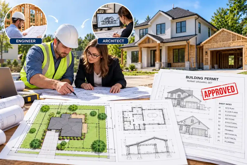
You’re ready to apply for a building permit, but the city asks for a complete set of construction drawings. You already have a floor plan, a property sketch, and perhaps a contractor’s estimate. Is that enough to submit your application? A complete permit drawing set is a coordinated collection of plans, details, schedules, calculations, and supporting documents that allows a building department to evaluate proposed construction against applicable requirements.
Depending on the project, the package may include a cover sheet, site plan, existing and proposed floor plans, exterior elevations, building sections, structural drawings, mechanical, electrical, and plumbing (MEP) plans, and energy compliance documents.
However, not every project requires every discipline. A simple detached shed may need a relatively small drawing package, while a home addition, accessory dwelling unit (ADU), or commercial building can require considerably more documentation.
The important distinction is between a drawing that illustrates your idea and a permit set that provides enough information for regulatory review and construction. This guide explains what each part of a permit drawing set includes, how the sheets work together, when professional engineering is necessary, and how to prepare a package that reduces avoidable permit corrections.
What Is a Complete Permit Drawing Set?
A permit drawing set is the collection of technical documents submitted to the relevant building or planning authority for approval of proposed construction. Its purpose is to describe the project clearly enough for reviewers to assess zoning, building safety, structural design, applicable building systems, and other requirements within their jurisdiction. A complete package typically answers several important questions.
Where will the work take place? What exists on the property today? What is being constructed or changed? How will the structure be supported? Which building systems are affected? What codes and design requirements apply?
For a detached garage, the drawings may focus on the site layout, floor plan, elevations, foundation, and framing. For a kitchen addition, the package may also need existing-condition plans, demolition details, roof connections, electrical changes, and energy documentation.
A commercial project can involve additional review disciplines, including fire protection, accessibility, civil engineering, and other specialized requirements.
A complete permit set is one that satisfies the applicable submission requirements for the specific project not one that simply contains the largest possible number of drawings.
Complete Permit Drawing Set Checklist
The following table summarizes the major drawing categories and their typical purposes.
| Drawing or Document | Information Included | When Commonly Needed |
|---|---|---|
| Cover Sheet | Project information, code summary, drawing index | Most formal drawing sets |
| Site Plan | Property boundaries, setbacks, building location, access | New buildings, additions, site work |
| Existing Conditions Plan | Current building layout and relevant features | Remodels, conversions, additions |
| Demolition Plan | Components to be removed or altered | Renovations and additions |
| Architectural Floor Plans | Rooms, dimensions, doors, windows, circulation | Building and interior construction |
| Exterior Elevations | Building height, openings, exterior materials | New buildings and exterior changes |
| Building Sections | Vertical construction and assembly details | New construction and complex alterations |
| Foundation Plan | Footings, slabs, reinforcement, anchors | Structural construction |
| Structural Framing Plans | Beams, joists, walls, roof framing, connections | Structural work |
| Electrical Plans | Lighting, receptacles, panels, circuits | Electrical installations |
| Plumbing Plans | Fixtures, supply, drainage, venting | Plumbing installations |
| Mechanical Plans | HVAC, ventilation, equipment | Mechanical work |
| Energy Documentation | Insulation, glazing, equipment, compliance calculations | Where energy codes apply |
| Fire and Life-Safety Plans | Egress, fire protection, relevant safety systems | When required |
| Civil and Grading Plans | Drainage, elevations, utilities, site improvements | Site-dependent projects |
| Engineering Calculations | Structural or system design verification | Where required |
| Supporting Documents | Surveys, reports, product approvals, specifications | Based on jurisdiction and scope |
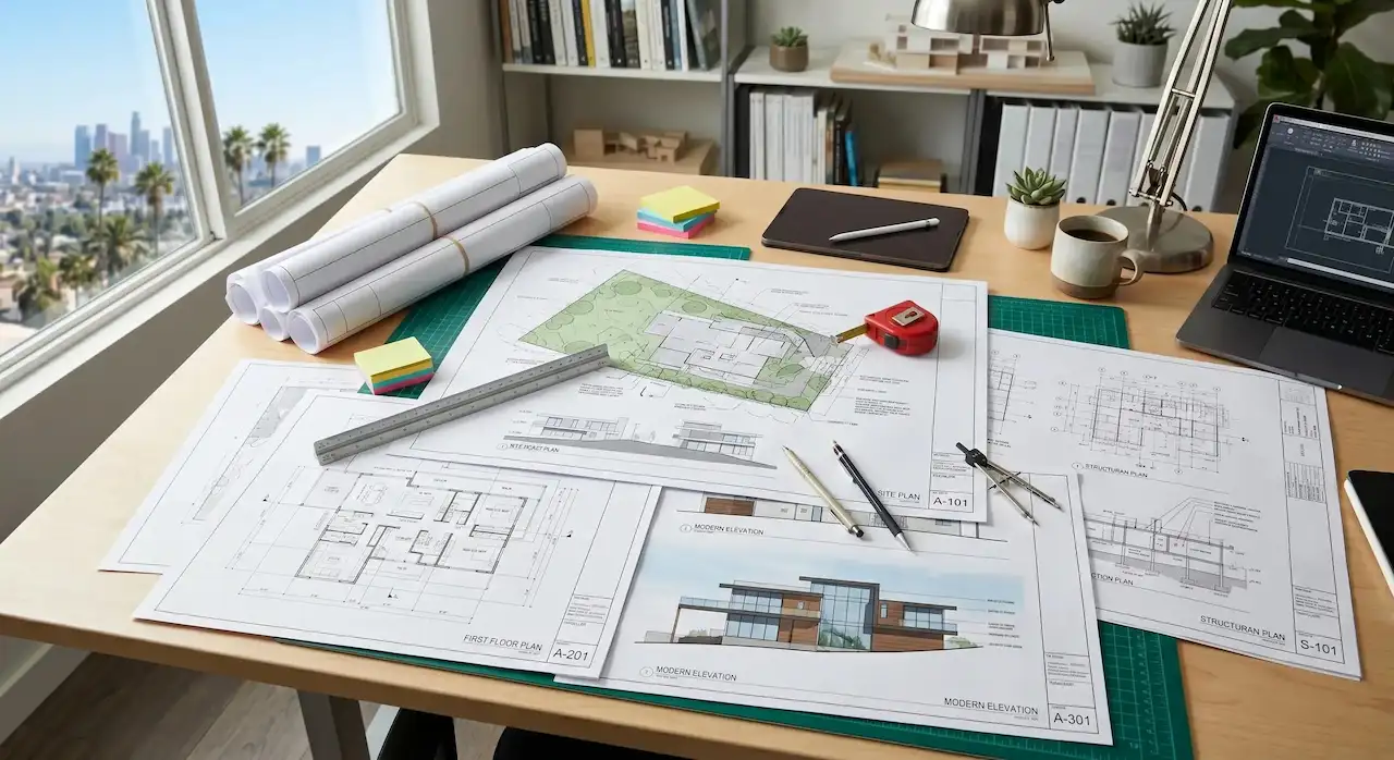
The table is a planning reference rather than a universal submission checklist. Your local building department may combine certain requirements, request additional information, or exempt specific work from portions of the standard package.
1. Cover Sheet and General Project Information
The cover sheet introduces the project and helps reviewers understand the contents of the drawing package. It commonly identifies the property address, project description, applicant or design team, drawing index, and relevant code information. For example, a home addition permit set may describe the project as a proposed one-story bedroom and bathroom addition to an existing single-family residence.
The cover sheet may also identify the applicable occupancy or construction information, depending on the project type and local requirements. Some jurisdictions require specific declarations, design criteria, or other administrative details. The cover sheet should agree with the permit application and the other drawing sheets.
If the application describes a detached garage but the drawings refer to an accessory dwelling unit, the inconsistency can create confusion during review.
What Is a Drawing Index?
A drawing index lists the sheets included in the permit package. It helps reviewers, contractors, and other project participants locate information quickly. A small residential project might use a few architectural and structural sheets. A larger project may include separate architectural, structural, civil, mechanical, electrical, and plumbing series. The index should be updated whenever sheets are added, removed, or revised.
2. Site Plan: Showing Where Construction Will Take Place
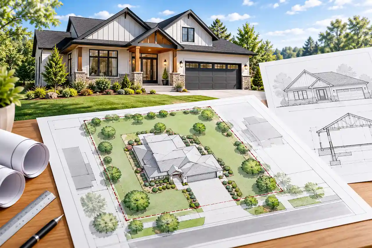
The site plan shows the relationship between the proposed construction and the property. It commonly identifies the existing building footprint, proposed work, property boundaries, setbacks, driveways, and relevant site features. For example, a detached garage permit set may include a site plan showing the proposed garage behind the house and its distance from the rear and side property lines.
A home addition site plan may show the existing footprint, new building area, and applicable lot coverage calculations. More complex projects may require information about grading, drainage, parking, utility connections, fire access, and other development conditions.
What Should a Permit Site Plan Include?
A typical site plan may need to identify:
- Property boundaries, dimensions, drawing scale, and north arrow
- Existing buildings and proposed construction footprints
- Required and proposed setbacks, plus relevant distances
- Driveways, access, easements, and utility information
- Lot coverage, drainage, grading, or parking details when required
A site plan may be prepared using suitable existing property information when the jurisdiction allows it. However, if certified boundaries or precise field measurements are required, a licensed survey may be necessary. A drafting site plan does not automatically replace a professional boundary survey.
3. Existing Conditions and Demolition Drawings
Existing-condition drawings document the building before the proposed work begins. They are particularly important for remodeling, garage conversions, additions, and projects involving changes to an existing structure. For example, a garage conversion permit package may need to show the existing garage door opening, walls, slab, windows, and roof configuration.
The proposed drawings can then identify how those features will change. A demolition plan separately shows what will be removed or altered. It may identify existing walls, doors, windows, fixtures, finishes, or structural components scheduled for demolition. The distinction matters because reviewers need to understand the relationship between the existing building and the proposed construction.
If a load-bearing wall will be removed, the permit set should also include appropriate structural information addressing the modification.
Why Accurate Existing Conditions Matter
Old construction drawings are not always reliable records of the current building. Previous renovations, undocumented alterations, and field variations may have changed the structure. A new design based on inaccurate existing dimensions can create conflicts during construction. Existing conditions should therefore be verified to the extent necessary for the project, including professional field investigation when concealed or structural conditions must be assessed.
4. Architectural Floor Plans
Architectural floor plans show the proposed arrangement of spaces within a building. They identify walls, rooms, doors, windows, stairs, fixtures, and relevant dimensions. For a new detached ADU, the floor plan may show the living room, kitchen, bedroom, bathroom, and utility areas. For a home addition, the plan should also explain how the new rooms connect to the existing house. The floor plan may include door and window labels that correspond to schedules elsewhere in the drawing set.
Depending on the project, reviewers may evaluate room dimensions, ceiling heights, circulation, emergency escape provisions, and other applicable safety requirements. The architectural drawings should be coordinated with the structural and MEP plans.
For example, a bathroom shown on the architectural plan should appear in the corresponding plumbing documentation.
5. Exterior Elevations
Exterior elevations show what the proposed building or altered structure will look like from its relevant sides. They may identify overall building height, roof configuration, exterior materials, doors, windows, and vertical dimensions. For a detached garage, the elevations may show the garage door openings, roof ridge height, and wall finishes. For a home addition, they may illustrate how the new construction integrates with the existing house. Elevations can help reviewers assess building height, exterior design, and applicable development requirements. The elevations must match the floor plans and roof drawings.
If the floor plan shows two windows on a wall but the elevation shows only one, the discrepancy may need correction.
6. Building Sections and Construction Details
Building sections show the structure as though it has been cut vertically. They help explain how the foundation, floors, walls, ceilings, and roof fit together.
For example, a section through a new residential addition may show the concrete footing, floor assembly, wall framing, insulation, ceiling height, and roof structure.
Construction details provide a closer view of important connections and assemblies. These may include wall-to-foundation connections, roof intersections, waterproofing, insulation, or other project-specific details. Sections and details are particularly important when the design cannot be fully explained through plans and elevations alone. They should also agree with the structural and energy documentation.
7. Foundation and Structural Drawings
Structural drawings explain how the building will support loads and maintain stability. Depending on the project, they may include foundation plans, framing layouts, structural sections, connection details, and engineering calculations.
For example, a detached garage permit set may require footing details, wall framing information, roof framing, and garage door header specifications. A second-story addition may require more extensive documentation because the existing house must support additional loads.
Foundation Plans
Foundation drawings may identify footings, slabs, piers, reinforcement, anchor bolts, and relevant dimensions. The design depends on structural loads, soil conditions, climate, and the applicable building requirements. A generic foundation detail is not automatically suitable for every property.
Structural Framing Plans
Framing plans show the arrangement of structural walls, beams, columns, joists, rafters, trusses, and other load-bearing elements. They may also identify connection requirements and relevant design specifications. For an addition, the structural drawings should explain how the new construction connects to the existing building.
Structural Calculations
Engineering calculations may be required to demonstrate that specific structural elements and connections satisfy applicable design requirements. Not every project needs custom calculations. Some conventional residential construction can follow accepted prescriptive provisions, while complex or nonstandard designs may require professional engineering.
8. Mechanical, Electrical, and Plumbing Plans
MEP drawings describe the systems that serve the building. These disciplines are often necessary for new dwellings, major renovations, commercial projects, and work involving new or modified building systems.
Mechanical Drawings
Mechanical plans may show heating, cooling, ventilation, exhaust, ductwork, and equipment locations. For example, a new home addition may require documentation explaining how the additional conditioned space will be heated and cooled. A commercial workshop may require additional ventilation or equipment information. The drawings should reflect the proposed building use and applicable mechanical requirements.
Electrical Drawings
Electrical plans may identify lighting, receptacles, switches, panels, circuits, equipment, and relevant electrical load information. For example, a detached garage with an EV charger may require documentation of the proposed electrical installation and available service capacity.
The electrical plans should match the architectural layout.
Plumbing Drawings
Plumbing plans may show fixtures, water supply, drainage, venting, and relevant utility connections. For a bathroom addition, the plans should explain how the new fixtures connect to the existing plumbing system. The required level of detail varies by project and jurisdiction.
9. Energy Compliance Documentation
Energy documentation demonstrates how the proposed construction addresses applicable energy-code requirements. It may include insulation values, window performance, air-sealing details, heating and cooling equipment specifications, and compliance calculations. The exact requirements depend on the project type, climate zone, adopted energy code, and local amendments.
For example, a new conditioned ADU may require more extensive energy documentation than an unconditioned storage building. A home addition may need to show the energy performance of new walls, roofs, windows, and other affected components. The energy forms and calculations should match the architectural and mechanical drawings.
If the window schedule changes, the energy documentation may need to be updated.
10. Fire Protection, Life Safety, and Accessibility
Some projects require additional documentation addressing fire protection, emergency egress, accessibility, or other life-safety provisions. The scope depends heavily on the building’s intended use.
For example, a small residential accessory building may have different requirements from a commercial office, restaurant, or warehouse.
Commercial permit sets may need to document accessible routes, exits, occupancy-related information, fire-rated assemblies, or fire protection systems. A building’s occupancy classification can influence which requirements apply. These documents should be coordinated with the architectural and MEP plans.
11. Civil Engineering, Grading, and Drainage Plans
Projects involving significant site development may require civil drawings in addition to the architectural and structural permit set. These documents can address grading, stormwater drainage, utility connections, paving, and other site improvements.
For example, a new commercial building may require plans showing parking areas, accessible routes, stormwater facilities, and utility infrastructure.
A residential addition on a steeply sloped property may also require more detailed site information. The extent of civil documentation depends on the property’s conditions and the jurisdiction’s development requirements. A basic residential site plan is not automatically equivalent to a complete civil engineering package.
12. Schedules, Specifications, and Supporting Documents
A permit set may include schedules that organize repeated building components. Door and window schedules can identify dimensions, types, and other relevant characteristics. Finish schedules, equipment schedules, and construction notes may also be included where necessary. Supporting documents can include surveys, geotechnical reports, structural calculations, product approvals, energy compliance forms, and other project-specific information.
For example, a prefabricated metal building permit package may include manufacturer engineering drawings along with a separately designed foundation. The supporting documents should correspond to the proposed project and its actual location.
What Is the Difference Between a Site Plan and a Complete Permit Drawing Set?
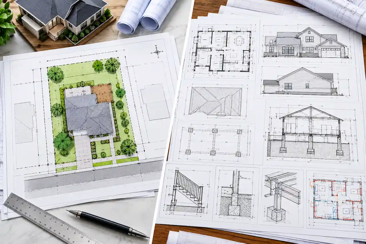
A site plan is one component of a larger permit drawing package. It primarily explains where construction is located on the property. A complete permit drawing set provides the additional information needed to understand the proposed building and its construction.
| Feature | Site Plan | Complete Permit Drawing Set |
|---|---|---|
| Property Boundaries and Setbacks | Commonly included | Included where relevant |
| Building Location | Included | Included |
| Interior Floor Layout | Usually not detailed | Included when required |
| Exterior Elevations | Generally separate | Included when required |
| Foundation Design | Generally separate | Included when required |
| Structural Framing | Generally separate | Included when required |
| Electrical and Plumbing | Limited site information, if relevant | Detailed where required |
| Energy Compliance | Usually separate | Included when applicable |
| Primary Purpose | Site placement and zoning review | Broader permit and construction review |
For example, a homeowner applying for a detached garage permit may need a site plan showing the garage’s location. However, the building department may also require floor plans, elevations, foundation details, and framing information. Submitting only the site plan would not necessarily satisfy the complete building permit requirements.
How Many Sheets Are in a Complete Permit Drawing Set?
There is no universal number of sheets required for a complete permit set. The appropriate sheet count depends on the construction scope, complexity, and jurisdiction. A small accessory structure may be documented on a limited number of sheets. A detached garage with a conventional design may require a site plan, architectural information, and structural details.
A home addition can involve existing-condition plans, demolition, proposed architectural drawings, foundation and framing plans, and MEP documentation. A commercial building may require substantially more sheets because multiple disciplines and regulatory requirements are involved. The objective is to provide complete and readable information rather than maximize the sheet count.
Permit Drawing Set Requirements by Project Type
Different construction projects require different combinations of drawings.
Detached Garage
A detached garage permit package commonly includes a site plan, floor plan, elevations, foundation details, and framing information. Electrical documentation may also be necessary when the garage includes lighting, receptacles, or other electrical equipment.
Home Addition
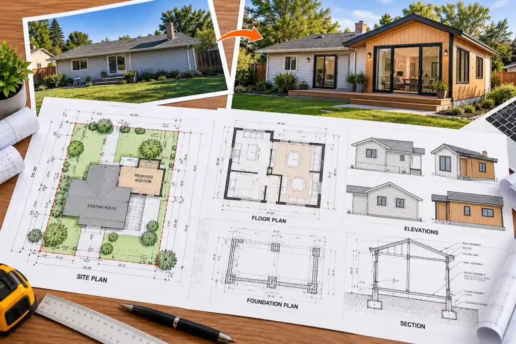
A home addition typically requires documentation of existing conditions, proposed construction, structural connections, and affected building systems. The drawings may also need to address roof tie-ins, energy compliance, and zoning calculations.
Accessory Dwelling Unit
An ADU generally requires a more comprehensive residential drawing package. Site, architectural, structural, MEP, and energy documentation may all be necessary. Garage conversions can require additional existing-condition and structural information.
Deck or Patio Cover
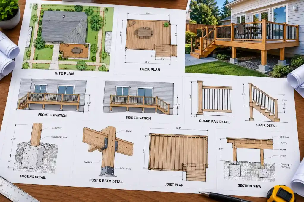
A deck permit package may include a site plan, footing details, framing plans, connections, stairs, and guard information. A patio cover may require additional roof framing and structural details.
Commercial Building
Commercial permit packages commonly involve architectural, structural, MEP, life-safety, accessibility, and site development information. The exact scope depends on the building use, size, occupancy, and jurisdiction.
Do Permit Drawings Need an Architect or Engineer?
Not every permit drawing set must be prepared by a licensed architect or engineer. Some jurisdictions allow homeowners or drafting professionals to prepare documents for qualifying residential projects. However, professional licensing laws and building department requirements can make licensed design services necessary for particular projects or disciplines.
For example, a simple residential site plan may not require a professional seal. A nonstandard structural design may require engineering calculations and drawings prepared by a licensed engineer.
Certain commercial projects may require architectural services, engineering services, or both. A professional seal should only be applied by a properly licensed professional within the scope of their authorized practice.
How Much Does a Complete Permit Drawing Set Cost?
The cost depends on the project type, size, complexity, and number of required disciplines. A site plan-only service is generally less expensive than a coordinated package containing architectural, structural, MEP, and energy documents. The availability of existing drawings, surveys, and site information can also affect the cost.
| Project or Service | Typical Scope Considerations |
|---|---|
| Site Plan Only | Property layout, setbacks, proposed footprint |
| Detached Garage | Site, architectural, foundation, framing |
| Home Addition | Existing conditions, architectural, structural, affected MEP |
| ADU | Site, architectural, structural, MEP, energy |
| Deck | Site, footing, framing, stairs, guards |
| Commercial Project | Architectural, structural, MEP, civil, life safety |
Additional expenses may include surveying, geotechnical reports, professional engineering, permit fees, and inspections. Before ordering a package, confirm exactly which sheets and services are included in the quote.
How Long Does It Take to Prepare a Permit Drawing Set?
The preparation timeline depends on the complexity of the project and the information available. A straightforward project with accurate property information and a clearly defined design may require less coordination than a project involving structural modifications or multiple building systems.
The process generally involves reviewing project requirements, gathering existing information, preparing drawings, coordinating disciplines, and checking the package for consistency. Engineering calculations, site investigations, and other professional services may affect the schedule. Municipal plan review is separate from drawing preparation.
A completed drawing package does not guarantee immediate permit approval.
Common Reasons Permit Drawing Sets Get Rejected
A permit drawing set may be returned for corrections when it lacks required information or contains conflicting details. One common problem is an incomplete site plan. Another is a mismatch between the architectural and structural drawings.
For example, the floor plan may show a large opening while the framing plan does not identify the required structural support.
MEP coordination can also cause problems when fixtures or equipment appear in different locations on different sheets. Missing energy documents, unclear foundation details, and outdated drawing revisions may lead to additional review comments. A coordinated quality check before submission can reduce these avoidable issues.
How to Organize a Permit Drawing Set
A well-organized permit set makes it easier for reviewers and contractors to find information. The drawing order may vary, but the package should follow a consistent structure. A typical set begins with general project information and site documentation, followed by architectural drawings, structural information, and applicable MEP sheets. Supporting calculations and reports may be included within the set or submitted as separate attachments according to the jurisdiction’s requirements.
Permit Drawing Set Quality-Control Checklist
Before submitting, verify that:
- The property address, project description, and drawing index are consistent
- The site plan and architectural drawings show the same building footprint
- Floor plans, elevations, sections, and structural details agree
- Required professional seals, calculations, and supporting reports are included
- MEP and energy documents match the latest architectural design
- All sheets use clear labels, dimensions, scales, and revision information
- The package follows the local building department’s submission checklist
A final coordination review is particularly important when different professionals prepare different parts of the package.
What Information Do You Need Before Ordering Permit Drawings?
Before requesting a complete permit drawing set, gather the property information and project details needed to establish the drawing scope. This usually includes the property address, project description, proposed dimensions, available surveys, existing building plans, photographs, and the local permit checklist. For remodeling or addition projects, accurate existing-condition information is especially important. For prefabricated structures, manufacturer drawings and structural specifications may be necessary.
If the building department has already issued corrections, provide the complete review comments so the required changes can be evaluated. The more clearly the project scope is defined, the easier it is to determine which drawing disciplines are necessary.
How to Get a Complete Permit Drawing Set
Start by identifying the project type and confirming the applicable permit requirements. Next, gather property records, existing plans, measurements, and proposed design information. The site and architectural drawings can then be developed to establish the project’s layout and construction scope. Structural and MEP documentation should be coordinated as required. Where necessary, licensed professionals should prepare or review engineering calculations and other regulated design documents.
Before submission, the complete package should be checked for consistency and compliance with the building department’s document requirements. If the reviewer issues comments, revise the affected drawings and follow the jurisdiction’s resubmittal process.
Get a Complete Permit Drawing Set From SitePlans.online
A complete permit drawing set helps explain your construction project to the building department before work begins. Whether you’re planning a detached garage, home addition, ADU, deck, metal building, or commercial improvement, the required drawings should reflect your actual project and local requirements.
Site Plans Online USA supports residential and commercial projects with site plans, architectural drafting, structural documentation, MEP coordination, and applicable engineering services. The appropriate scope depends on the project type, location, and building department checklist.
Need a complete permit drawing set for your project?
Visit SitePlans.online to request a quote and share your project details, existing documents, and permit requirements.
Frequently Asked Questions About Permit Drawing Sets
1. What is included in a complete permit drawing set?
A complete permit drawing set may include a cover sheet, site plan, floor plans, elevations, building sections, structural drawings, MEP plans, energy documentation, and supporting calculations. The required contents depend on the project and jurisdiction.
2. Is a site plan enough to get a building permit?
Sometimes, for limited work where the jurisdiction only requires site information. However, most new buildings and substantial additions also require architectural, structural, and other construction documents.
3. How many drawings do I need for a building permit?
There is no universal number. The sheet count depends on the project size, complexity, applicable codes, and local submission requirements. Completeness matters more than the number of pages.
4. Do permit drawings need to be stamped by an engineer?
Not always. Some residential projects can use drawings prepared without professional seals. Structural engineering or other licensed design services may be required for certain projects, depending on state law and local requirements.
5. What is the difference between permit drawings and construction drawings?
Permit drawings are prepared to demonstrate compliance for regulatory review. Construction drawings provide the information needed to build the project. The same coordinated drawing set may serve both purposes, but some projects require additional construction details beyond the permit submission.
6. Can I submit my own drawings for a building permit?
Some jurisdictions allow homeowner-prepared drawings for qualifying residential projects. The drawings must still meet the applicable submission standards, and certain work may require licensed professionals.
7. Do I need MEP drawings for a residential permit?
It depends on the work. Projects involving electrical, plumbing, or mechanical installations may require separate drawings or trade permit documentation. A simple project without those systems may have fewer requirements.
8. How much does a complete permit drawing set cost?
Costs vary based on the project type, size, complexity, required disciplines, and professional services. A site plan-only package generally costs less than a complete architectural, structural, MEP, and energy drawing set.
9. What happens if my permit drawing set is incomplete?
The building department may reject the application as incomplete or issue correction comments requesting additional information. The missing or inconsistent documents generally must be addressed before approval.
10. Can one company prepare the entire permit drawing set?
Some providers coordinate multiple drawing disciplines, while others specialize in specific services. The provider should clearly identify which drawings are included and which require separate licensed professionals or consultants.
- Do Permit Drawings Need an Engineer or Architect?
- What Does a Complete Permit Drawing Set Include?
- Deck Permit Drawings: Footings, Posts, Beams, Joists, Guards & Site Plan
- Home Addition Permit Plans: From Existing House to Approved Drawing Set
- Metal Building Permit Plans: Manufacturer Drawings Are Usually Not the Whole Permit Set
Get Your Permit Drawing Scope Reviewed
Send us the property address and project details. We’ll help identify the likely drawing scope and next step.

Engineer Wasim
Civil/Structural Engineer and founder behind Site Plans Online USA. His permit-drafting experience dates back to 2015, supporting residential, commercial, structural and site-development projects.
Learn More About Site Plans LLC →